**My Journey with OpenGL :**
Hi, I'm [Remy Lambert](https://github.com/remlamb?tab=repositories) and this is a quick preview of the concept present in my 3D rendered Scene made with OpenGL.
## **First quick Reminder : **
### What's a Mesh ?
A mesh is a 3D object, generally an array of data containing the positions of vertices. The vertices are the points that make up the shape of the object. We need the geometric position of these points to translate them into our scene. For OpenGL, meshes are created from several triangles.
### What's OpenGL ?
OpenGL (Open Graphics Library) is an API (application programming interface) used for 2D and 3D rendering in graphics applications. OpenGL interacts with our graphics card. For my scene I use OpenGL ES 3.0, ES stands for Embedded system. It's a mix between OpenGL 3 and OpenGL 4.3 OpenGL ES 3.0 is compatible with multiple platforms. Used for this graphics loop: initialising things, clearing our screen, drawing, swapping buffers, clearing and destroying everything. OpenGL is in charge of rasterization, the system that converts our mesh vertices into pixels for our screen.
## **Final Scene**
Here are the different key principles applied in my scene. Some elements have values that can be modified directly in the 3d scene using an imgui window.
I've created 3 predefined presets that change the atmosphere of the scene.
Feel free to try some cool settings
### Elements * HDR Texture * OBJ Model * ShadowMap * Deferred Shading and SSAO * PBR with IBL * Instancing * Cubemap * PostProcessing Bloom and Filter

using Solid Blue Preset

using Ambiant Purple Preset

using Powerfull Pink Preset

I will talk about each part in the order of the drawing in the pipeline.
## **Loading**
### HDR Texture
HDR Texture or High Dynamic Range are textures that store a much wider dynamic range of luminosity. They capture details especially when it's very bright.
For us, the major change was to write their data as floats. And to modify the format references for the openGL texture binding system.
And for rendering, we had to put them back into a visual reference that our monitors could understand, thanks to tone mapping. The value must be between 0.0 and 1.0 (Low Dynamic Range).
Tone mapping that I apply at the end to my framebuffer which handles PostProcessing
### OBJ Model
The image above shows the rendering of my chat mesh on RenderDoc.
To achieve this, we used Assimp, a cross-platform open-source library that reads data from our 3D model, here rendered in .OBJ format.
.obj is a file that stores information such as vertex positions, normals, etc.
We store them to translate them to openGL.
## **Shadow Map**
### Depth Map
Firstly, shadows are a consequence of light.
There are several types of light caster, but here we're just going to talk about directional light.
In fact, in my scene, only the directional light emits shadows. It's supposed to represent the sunlight that's drawn in my skybox.
The depth map is a texture designed to display the depth of the elements according to the point of view of the light producing the shadows.
We give our objects this texture so that we can apply the shadow during the drawing phase.

Exemple of a dethmap

We can see the shadow of the table on the floor
~~~~~~~~~~~~~~~~~~~~~~~~~~~~~~~~~ float ShadowCalculation(vec4 fragPosLightSpace) { vec3 projCoords = fragPosLightSpace.xyz / fragPosLightSpace.w; projCoords = projCoords * 0.5 + 0.5; if (projCoords.z > 1.0) { return 0.0; } // get closest depth value from light's perspective float closestDepth = texture(shadowMap, projCoords.xy).r; float currentDepth = projCoords.z; vec3 lightDir = -directionalLightDirection; //normalize(lightPos - fragPos); float bias = 0.006; float shadow = 0.0; vec2 texelSize = vec2(1.0) / vec2(textureSize(shadowMap, 0)); for(int x = -1; x <= 1; ++x){ for(int y = -1; y <= 1; ++y){ float pcfDepth = texture(shadowMap, projCoords.xy + vec2(x, y) * texelSize).r; shadow += currentDepth - bias > pcfDepth ? 1.0 : 0.0; } } shadow /= 9.0; return shadow; } ... vec4 FragPosLightSpace = lightSpaceMatrix * fragWorldPos; float shadow = ShadowCalculation(FragPosLightSpace); Lo += (1.0 - shadow) * (kD * albedo / PI + specular) * radiance * NdotL; ~~~~~~~~~~~~~~~~~~~~~~~~~~~~~~~~~
## **Deferred Shading and SSAO**
### GBuffer ?
The G-Buffer for Geometry buffer is a frame buffer that stores information about the objects in the scene.
Here I'm storing positions in the gPosition texture, normals in the gNormal texture and colours in the gAlbedo texture.
We'll see how to use the PBR later, but I need other information to render an object.
To avoid creating a new texture I store these values in the Alpha value of the textures in my GBuffer.

gPosition Texture

gNormal Texture

gAlbedo Texture
Note: My instantiated grass is not in this buffer because it uses a blending system for its transparency which is not compatible with defered shading.
With this system, the Gbuffer just needs to receive the geometry from the objects and then render it using the light pass.
### SSAO
SSAO or Screen Space Ambient Occlusion is a way of adding a shadow effect in occluded areas.
SSAO adds a sense of realism and depth, and is coupled with the AO value or texture that we'll look at later in the PBR section.
The SSAOMap is calculated using the position between objects and their depth.
We use a kernel noise texture in the ssao map creation to take the values for the surrounding position. This is useful for avoiding patterns that are too uniform.

Noise
After having this SSAOMap we blur it for a more pleasant rendering.

SSAO Map without blur
## **PBR and Lightning**
### PBR
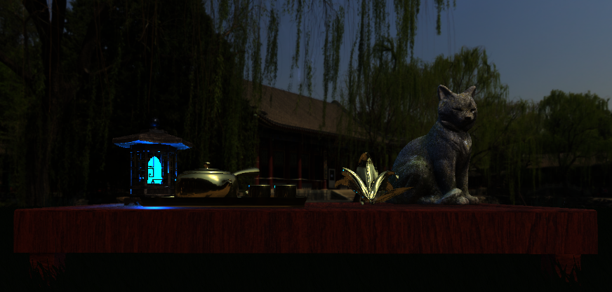
The biggest part of the programme is the laws governing the rendering system.
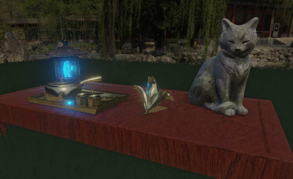
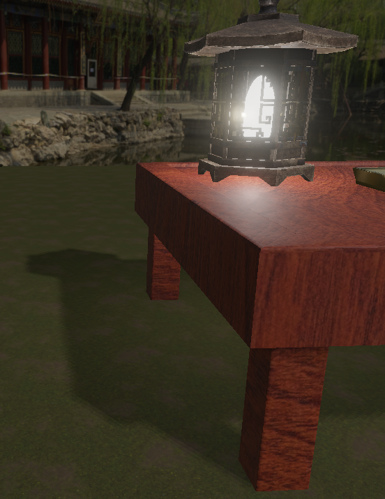
The scene uses PBR or Physically Based Rendering.
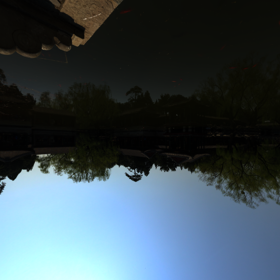
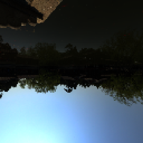
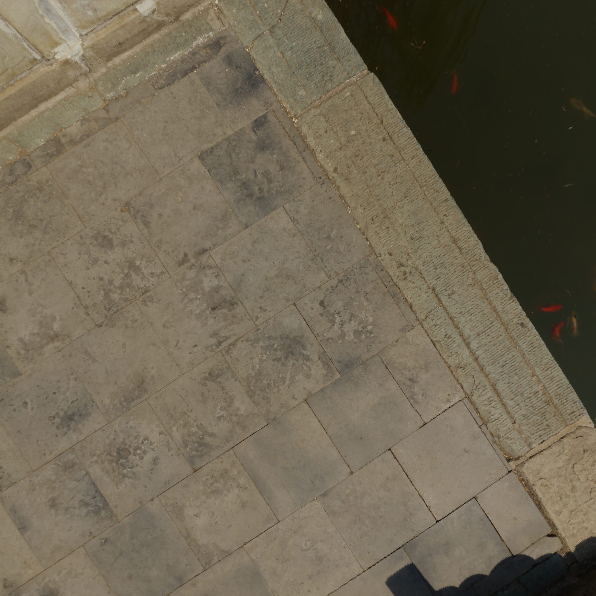
The aim is to simulate the behaviour of light on objects and their surfaces as realistically as possible.
Objects have given textures to represent their behaviour when exposed to light.
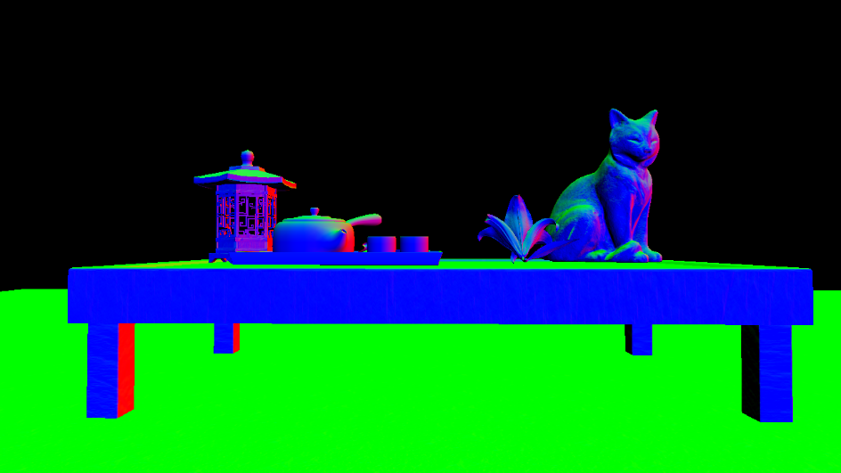
Roughness: the higher this value, the more light is diffused in multiple directions. A low value corresponds to a smooth surface.
Metalic: the higher the value, the more the object will reflect light.
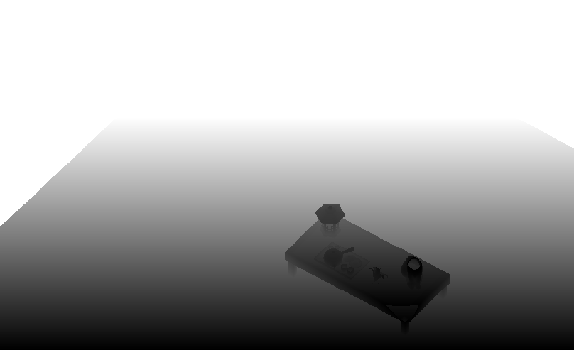
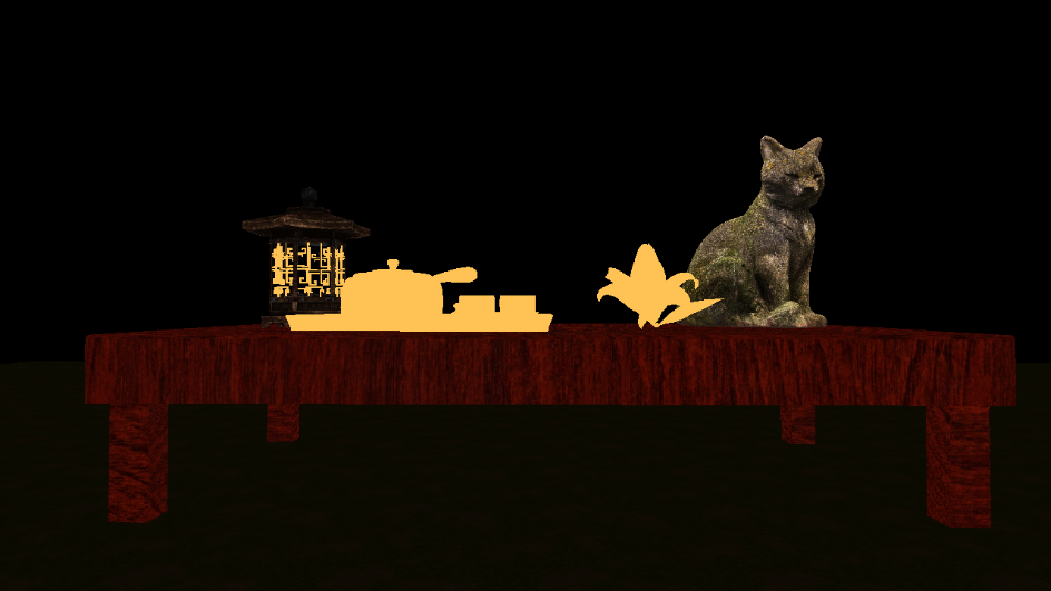
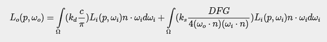
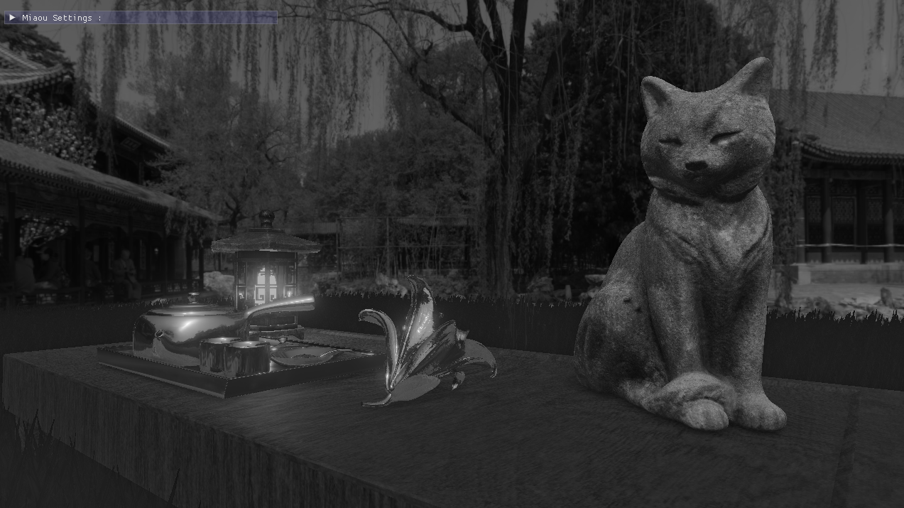
AO: to simulate object shadows in certain hollows
As seen above, the AO adds a depth effect to the object itself.
You can experiment on these three concepts on the flower in my scene by tweaking the values.

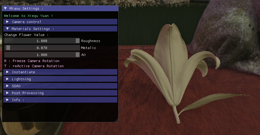
Roughness visual proprieties

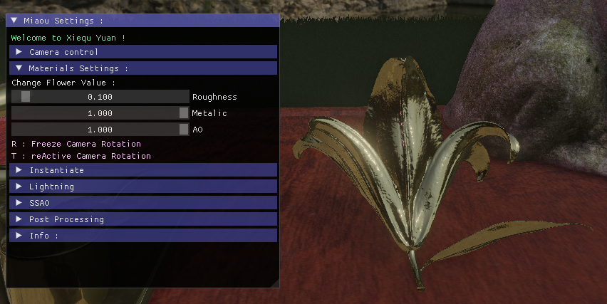
Metalic visual proprieties
PBR also includes the principle of energy conservation.
~~~~~~~~~~~~~~~~~~~~~~~~~~~~~~~~~ // material properties vec3 albedo = texture(gAlbedo, TexCoords).rgb; float metallic = texture(gPosition, TexCoords).a; float roughness = texture(gNormal, TexCoords).a; float ao = texture(gAlbedo, TexCoords).a; float ssao = texture(SSAOMap, TexCoords).r; float combined_ao = ssao * ao; // input lighting data vec3 N = mat3(inverseViewMatrix) * texture(gNormal, TexCoords).rgb; ; vec3 V = normalize(camPos - WorldPos); vec3 R = reflect(-V, N); // calculate reflectance at normal incidence; vec3 F0 = vec3(0.04); F0 = mix(F0, albedo, metallic); // reflectance equation vec3 Lo = vec3(0.0); // calculate per-light radiance vec3 L = normalize(-directionalLightDirection); vec3 H = normalize(V + L); //float distance = length(lightPositions[i] - WorldPos); //float attenuation = 1.0 / (distance * distance); vec3 radiance = directionalLightColor; // Cook-Torrance BRDF float NDF = DistributionGGX(N, H, roughness); float G = GeometrySmith(N, V, L, roughness); vec3 F = fresnelSchlick(max(dot(H, V), 0.0), F0); vec3 numerator = NDF * G * F; float denominator = 4.0 * max(dot(N, V), 0.0) * max(dot(N, L), 0.0) + 0.0001; vec3 kS = F; vec3 kD = vec3(1.0) - kS; kD *= 1.0 - metallic; float NdotL = max(dot(N, L), 0.0); ... ~~~~~~~~~~~~~~~~~~~~~~~~~~~~~~~~~
### IBL
IBL or Image Based Lightning
We use the PBR values and the brdf LUT to simulate the reflection or not of the skybox on objects.
For this we introduce some new Texture :
From left to right : A Part of my skybox, we will learn more in the Cubemap section. a Prefilter Map and a Irradiance Map
For this effect to work, we need an HDR skybox texture.
Now that we have information on the intensity of light in our sky. We can approximate which areas are the most intense.
A brdf lookup texture :

This is a texture that represents how light propagates around the object.
This is an approximation because as we see earlier the original function is an integral.
This is the integral, we try to approximate : Cook-Torrance Reflectance Equation.
We split it in two, first part is for the diffuse and second for the specular.
Admire the work with the reflection of the skybox on the golden tea set or by setting the flower values to high metalic and low roughness thanks to the IBL. ~~~~~~~~~~~~~~~~~~~~~~~~~~~~~~~~~ // ambient lighting (we now use IBL as the ambient term) F = fresnelSchlickRoughness(max(dot(N, V), 0.0), F0, roughness); kS = F; kD = 1.0 - kS; kD *= 1.0 - metallic; vec3 irradiance = texture(irradianceMap, N).rgb; vec3 diffuse = irradiance * albedo; // sample both the pre-filter map and the BRDF lut and combine them together as per the Split-Sum approximation to get the IBL specular part. const float MAX_REFLECTION_LOD = 4.0; vec3 prefilteredColor = textureLod(prefilterMap, R, roughness * MAX_REFLECTION_LOD).rgb; vec2 brdf = texture(brdfLUT, vec2(max(dot(N, V), 0.0), roughness)).rg; specular = prefilteredColor * (F * brdf.x + brdf.y); vec3 ambient = (kD * diffuse + specular) * combined_ao; vec3 color = ambient + Lo; ~~~~~~~~~~~~~~~~~~~~~~~~~~~~~~~~~
### Another Light !
I add a simple light point, with custom color to add a better atmosphere to the scene but it also show how the PBR can render cool reflection with multiple light source
~~~~~~~~~~~~~~~~~~~~~~~~~~~~~~~~~ for(int i = 0; i < 1; ++i) { // calculate per-light radiance L = normalize(lightPositions[i] - WorldPos); H = normalize(V + L); float distance = length(lightPositions[i] - WorldPos); float attenuation = 1.0 / (distance * distance); radiance = lightColors[i] * attenuation; // Cook-Torrance BRDF NDF = DistributionGGX(N, H, roughness); G = GeometrySmith(N, V, L, roughness); F = fresnelSchlick(max(dot(H, V), 0.0), F0); numerator = NDF * G * F; denominator = 4.0 * max(dot(N, V), 0.0) * max(dot(N, L), 0.0) + 0.0001; specular = numerator / denominator; // kS is equal to Fresnel kS = F; kD = vec3(1.0) - kS; kD *= 1.0 - metallic; NdotL = max(dot(N, L), 0.0); // add to outgoing radiance Lo Lo += (kD * albedo / PI + specular) * radiance * NdotL; } ~~~~~~~~~~~~~~~~~~~~~~~~~~~~~~~~~
## **Instancing**
### How to draw multiple object at once
In order to optimize, instead of drawing a mesh 4000 times that draws a clump of grass.
I store all the position values of my meshes to make a single draw call for my 4000 elements.
I also tried to add a wind movement effect through the vertex buffer.
~~~~~~~~~~~~~~~~~~~~~~~~~~~~~~~~~ glm::mat4* modelMatrices; ... for (unsigned int zIndex = 0; zIndex < amount_; zIndex++) { for (unsigned int xIndex = 0; xIndex < amount_; xIndex++) { glm::mat4 model = glm::mat4(1.0f); ... model = glm::translate(model, glm::vec3(x, y, z)); modelMatrices[i] = model; i++; } } ~~~~~~~~~~~~~~~~~~~~~~~~~~~~~~~~~
### An other Optimisation ?
To optimize, I also use a global state change for opengl on some of my models, which allows only the front face of an object to be drawn.
This is called back face culling. Front face culling also exists, but it's the opposite principle.
For example, it's not used to render my cube map or flat objects like floor plane or grass quad.
~~~~~~~~~~~~~~~~~~~~~~~~~~~~~~~~~ // Enable Face culling glEnable(GL_CULL_FACE); glCullFace(GL_BACK); ~~~~~~~~~~~~~~~~~~~~~~~~~~~~~~~~~
## **Cubemap**
### 6 Faces ?
In the beginning, we simply gave 6 textures to openGL to get a cube that simulated a skybox.
Then we used a HDR file to draw a new cubemap that give us more information.
~~~~~~~~~~~~~~~~~~~~~~~~~~~~~~~~~ // pbr: setup cubemap to render to and attach to framebuffer // --------------------------------------------------------- glGenTextures(1, &envCubemap); glBindTexture(GL_TEXTURE_CUBE_MAP, envCubemap); for (unsigned int i = 0; i < 6; ++i) { glTexImage2D(GL_TEXTURE_CUBE_MAP_POSITIVE_X + i, 0, GL_RGB16F, 4096, 4096, 0, GL_RGB, GL_FLOAT, nullptr); } glTexParameteri(GL_TEXTURE_CUBE_MAP, GL_TEXTURE_WRAP_S, GL_CLAMP_TO_EDGE); glTexParameteri(GL_TEXTURE_CUBE_MAP, GL_TEXTURE_WRAP_T, GL_CLAMP_TO_EDGE); glTexParameteri(GL_TEXTURE_CUBE_MAP, GL_TEXTURE_WRAP_R, GL_CLAMP_TO_EDGE); glTexParameteri(GL_TEXTURE_CUBE_MAP, GL_TEXTURE_MIN_FILTER, GL_LINEAR); glTexParameteri(GL_TEXTURE_CUBE_MAP, GL_TEXTURE_MAG_FILTER, GL_LINEAR); // pbr: convert HDR equirectangular environment map to cubemap equivalent // ---------------------------------------------------------------------- equirectangular_to_cubemap_pipeline.SetInt("equirectangularMap", 0); equirectangular_to_cubemap_pipeline.SetMat4("projection", captureProjection); hdr_cubemap.BindTextureHDR(GL_TEXTURE0); glViewport(0, 0, 4096, 4096); ~~~~~~~~~~~~~~~~~~~~~~~~~~~~~~~~~
## **PostProcessing**
### Bloom effect
The bloom effect is generated from the render buffer by detecting all scene values greater than 1.0, thanks to HDR.
This texture is downscaled and then upscaled again.
It is then applied to the final scene
A [cool Article](http://gangles.ca/2008/07/18/bloom-disasters/) that show how bloom was affected elements before try to make it physically based.
We can see the texture that the buffer receive and next the elements with high intensity

Elements with high intensity after down and up scale

### Simple Color Filter
After applying tone mapping and gamma correction, I can activate a black and white filter.
It reads the color elements of the buffer and changes them to grayscale.
Cool, it looks like a Kurosawa film!
~~~~~~~~~~~~~~~~~~~~~~~~~~~~~~~~~ // tone mapping result = result / (result + vec3(1.0)); //gamma correct const float gamma = 1.8; result = pow(result, vec3(1.0 / gamma)); FragColor = vec4(result, 1.0); ... if(BnWFilter){ float average = 0.2126 * FragColor.r + 0.7152 * FragColor.g + 0.0722 * FragColor.b; FragColor = vec4(average, average, average, 1.0); } ~~~~~~~~~~~~~~~~~~~~~~~~~~~~~~~~~
## **Conclusion**
First of all, thank you for reading.
In addition to our course, several elements of the scene are realised thanks to [LearnOpenGL website](https://learnopengl.com/).

I also used RenderDoc for graphical debugging.

This is a powerful tool that can give us information about the current position of the mesh or any information given to and by the shader.
Uniformity can also be visualised. We can also access an edit shader directly from the RenderDoc. Can preview texture on input or output from frame or gbuffer. Etc...
The Death of RenderDoc

He die for me :(

For the future I would like to improve the render time, currently the scene takes a good 10 seconds to load the models and textures. Surely optimisable with multithreading for example. Also some of the methods are a bit outdated. Loading fbx models and implementing raytracing would be a good follow-up.